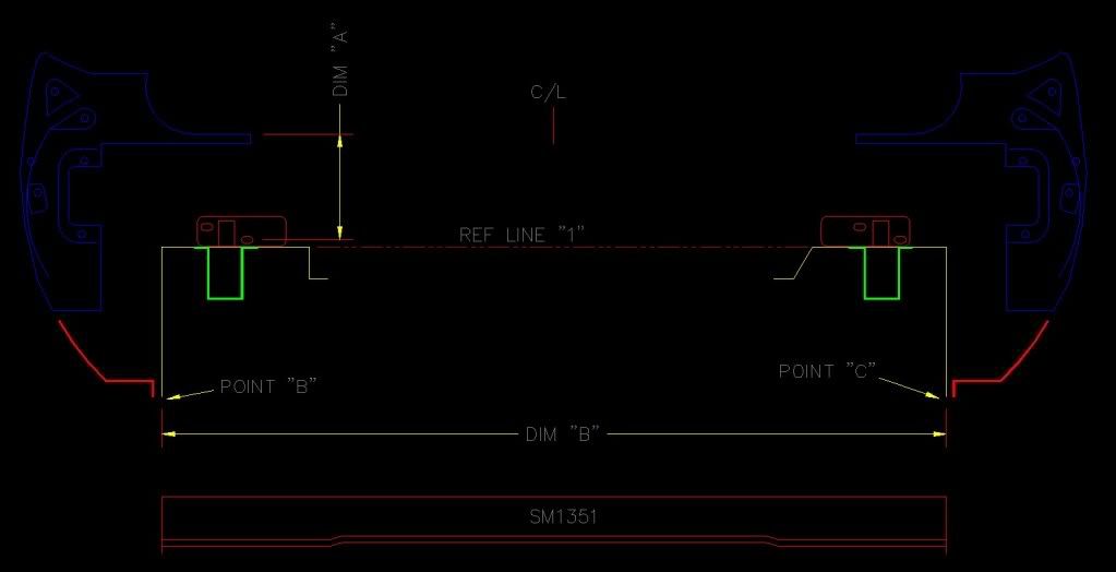
Synopsis:
Replacing trunk floors (right and left) and SM1351 rear x-member cuz' PO ran with rotten exhaust which ate them up.
No evidence of prior collision repair, etc. in this area.
Method:
Remove & replace rear taillight panel with "FORD tooling" one at the same time. (Done ONLY for best access to work area)
QUESTION:
How can "dim A" be varied so that the slotted holes in the bumper mount reinforcement brackets line up with the same sloted holes in the taillight panel? This dimension needs to be increased 3/4" for the slots to line up.
The frame rails are strong and in great shape and have very little vertical flex. The rear is on jack stands, supported by the body just in front of the rear wheels. The weight of the rear axle/springs is pulling downward on the frame rails. When the old parts were removed nothing moved more than 1/16".
Dim B and SM1351 were perfect and the top of SM1351 is flush with the tops of the frame rails.
The rear valence fits great left/right, but the top edge is 1/2" or so below Ref line 1.
If I force the frame rails downward (I can) so ref line 1 and the top edge of the valence are flush, the bumper bolt holes line up perfectly, BUT there is a big problem. The two trunk floors are much too low at the joint where they spot weld to the wheelhouses. Points B and C DO work out better though.
The bumper mount bracket slots, on the ones I removed were "hogged out" downward until there was no material left at all on the lower holes. You could barely get a socket on the lower 2 bolts because they touched the trunk floors.
I'm a pretty good investigator (I used to be a GA State Trooper). My Dad was the shop foreman in the Body Shop of the Lincoln/Merc dealer, (I grew up in the body shop and knew what to look for) I could not find anything that indicated the stuff I took off was done anywhere except on the assembly line.
