Author Topic: 67 San Jose -reassembling the rear valance  (Read 7188 times)

Offline J_Speegle

  • Administrator
  • Hero Member
  • *****
  • Posts: 24620
Re: 67-reassembling the rear valence
« Reply #15 on: November 11, 2017, 02:42:09 PM »
I seem to be following roddster's posts around the forum.

I gather the valance is primed in red oxide (RO) on both sides.
It is then hung on either 3 (most common) or 2 screw holes in from each end.

Believe you are confusing the location of the two mounting screws (second or third position from the ends) with the number. I've never found a San Jose car with three mounting screws installed before exterior paint


The bracket is already in place. The bolt squished any sealant present.

Yes the rear bumper guard bracket

The outside of car is sealed/primed. The trunk is not, but gets overspray.

The trunk would have gotten some red oxide primer Items like the trunk lid (Mustang)  hinges back side of the taillight panel and a half** attempt to spray some on the quarters and forward towards the interior. No attempt to coat the surfaces with the gray primer filler

Some small amount might land on backside of valance.

Think you might be thinking exterior color?  Rear valance hung after light gray primer coat but before exterior color. Some dusting from overspray from all the paint floating around, what mist might be introduced through the gas tank opening, the ends hanging down and the paint passing through the open back up light holes and pushing off the rear cross member through those holes

Trunk is painted first and some overspray along tailight panel might land on back side of valance.

Normally the inside of the trunk and back side of the taillight panel got a decent coat of paint where it would be visible from standing and looking into the trunk. No effort was made to coat all the small hidden panels, supports and such especially towards the front, up under the rear window, bottom of the quarter panels and places like the corners where the quarter panel extensions and quarter panels meet
Jeff Speegle

Anything worth doing is worth doing concours ;)

Offline Bossbill

  • Hero Member
  • *****
  • Posts: 3283
  • In the middle of project hell
Re: 67-reassembling the rear valance
« Reply #16 on: November 14, 2017, 09:08:04 PM »
I've searched through the 1967 Mustang Part & Body Illustrations and -- of course -- the rubber washer (red arrow, second pic) doesn't appear in there.
 
But my question concerns the built-in nut (yellow arrow) in the bracket.
Here is the bracket all by itself:


and here it is waiting to be installed:


The yellow dashed line indicates where a bolt w/washer would pass through the body, the gas tank flange, some black goop and into the built-in nut. The hole in the body is smaller (0.4") than the barrel end of the built-in nut (0.5") so either you need to install a rubber washer on top of the built-in nut, we enlarge the factory hole to 0.5" or we simply allow the nut to dig into the body. The later just seems wrong.
Bill
Concours  Actual Ford Build 3/2/67 GT350 01375
Driven      6/6/70 0T02G160xxx Boss 302
Modified   5/18/65 5F09A728xxx Boss 347 Terminator-X 8-Stack
Race        65 2+2 Coupe conversion

Offline J_Speegle

  • Administrator
  • Hero Member
  • *****
  • Posts: 24620
Re: 67-reassembling the rear valance
« Reply #17 on: November 14, 2017, 09:18:06 PM »
The yellow dashed line indicates where a bolt w/washer would pass through the body, the gas tank flange, some black goop and into the built-in nut. The hole in the body is smaller (0.4") than the barrel end of the built-in nut (0.5") so either you need to install a rubber washer on top of the built-in nut, we enlarge the factory hole to 0.5" or we simply allow the nut to dig into the body. The later just seems wrong.

I don't see any signs of a gasket or sealer between the cross member and the rear bumper brackets and see no problem with just allowing for the nut to be held tightly to the cross member as part of the retaining especially considering the second retaining bolt and j clip (in that location)

Would not enlarge the hole to allow the nut to pass through the hole. More likely to create a lose fit and not what was done originally
Jeff Speegle

Anything worth doing is worth doing concours ;)

Offline Bossbill

  • Hero Member
  • *****
  • Posts: 3283
  • In the middle of project hell
Re: 67-reassembling the rear valance
« Reply #18 on: November 14, 2017, 11:45:23 PM »
Thanks Jeff. I saw no evidence either, but the bracket had a bunch of surface rust. The repops are flat without the raised barrel and would actually work better -- flat against flat.
Bill
Concours  Actual Ford Build 3/2/67 GT350 01375
Driven      6/6/70 0T02G160xxx Boss 302
Modified   5/18/65 5F09A728xxx Boss 347 Terminator-X 8-Stack
Race        65 2+2 Coupe conversion

Offline Bossbill

  • Hero Member
  • *****
  • Posts: 3283
  • In the middle of project hell
Re: 67 San Jose -reassembling the rear valance
« Reply #19 on: February 04, 2018, 11:39:24 PM »
I was cleaning, painting and POing some parts and got back to this area. A few things have always bothered about this area and I think I know why.
During a mock-up of all the bolts required for this assembly, I looked up the AMK kit for the bracket and see that you get a pair of Cad iridescent yellow finish hex bolts and the same finish on a pair of PoziDrive bolts. This lead me down the bunney trail of exactly where do these go? Are these correct? I had two PosiDrives in my old parts off the car, but my description sheet for those was missing.

First, here is a snip of the Body Assembly Manual detailing that area and to items I refer in the comments following. Highlighted in red are the items in question.


Here is Jeff's post in this thread: in which he shows this pic:
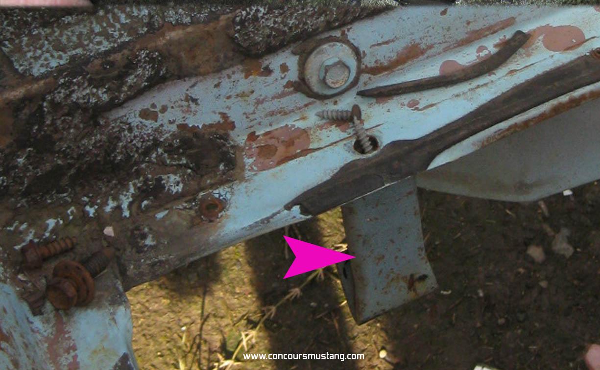

This shows the rearward facing bumperette bracket attaching bolt with 1" washer. According to the Body Assembly Manual Pg 63 this hex bolt is item "4L" and is part 377357-S36. S36 denotes this as having a Cad iridescent yellow finish.
Here it is covered in paint, correctly. The finish is the most important part, I think, even though it's covered in paint later.
One of the other Cad iridescent yellow bolts is part '5Q', a PoziDrive bolt listed as a 379949-S36. The PoziDrive screws the bumperette itself to the bottom of the bracket and is very visible at the bottom of the valance.
It should also be noted that the AMK kit I referenced earlier has the correct 4 square J-nuts for both bolt '5Q' and bolt '4L', a 378681-S2.
We'll get to one more pair of Cad iridescent bolts used in the bumperette assembly in a bit ...

However, two items are missing in the bracket build up.
In this thread, earlier, I asked why the square protruding nut on the bracket didn't have any allowance in the body for it to fit.
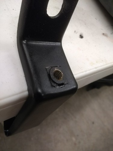

It turns out the factory originally did have a shim listed to keep the square nut from digging into the body, noted in the Assembly manual as '4Y'. IMO, it appears the shim never made it into cars as the gas tank goop filled that need. Or they just left it out.

Speaking of gas tanks and shims, the bolt that went vertically into the bumperette bracket after the tank was installed has been a bit of a mystery to me. In the Assembly Manual it's listed as part '4M', a 378242-S2. In Jim-Speak, a 5/16-18X1 1/4HH,REC,DISC LKW,LD PT.
Most of these bolts appear to have a built in washer with serrated teeth in 1967. However, my correctly date coded gas tank marks indicate a 0.75-0.80 disc without any teeth. My parts car doesn't show teeth marks here either.
Help here appreciated.

Finally, the bumperette itself.
I already mentioned the bottom PoziDrive bolt as it screws the bumperette into the bracket assembly at the bottom. However, the top bolt is considered part of the bumperette and is listed as part '5R', a hex bolt 377357-S36 also in Cad iridescent yellow. Strange that I've not noticed this bright gold part on restored cars. Is it not used in production even if it's listed?
This pic shows the empty hole for the bumperette, right above the bracket bolt.


As a parting shot, the Assembly Manual shows the bumperette top J-nut, '5F', is a 379670-S100. S100 denotes a special finish of various types over the years, but I don't know as to what it is here.
Help here appreciated.
Bill
Concours  Actual Ford Build 3/2/67 GT350 01375
Driven      6/6/70 0T02G160xxx Boss 302
Modified   5/18/65 5F09A728xxx Boss 347 Terminator-X 8-Stack
Race        65 2+2 Coupe conversion

Offline J_Speegle

  • Administrator
  • Hero Member
  • *****
  • Posts: 24620
Re: 67 San Jose -reassembling the rear valance
« Reply #20 on: February 05, 2018, 12:20:05 AM »
It turns out the factory originally did have a shim listed to keep the square nut from digging into the body, noted in the Assembly manual as '4Y'. IMO, it appears the shim never made it into cars as the gas tank goop filled that need. Or they just left it out.

Think your overstating things a bit. The drawing shows that Ford considered and drew up plans to use a shim this doesn't not mean it ever made it into production and/or applications. May have been used on other cars and applications.

Finally, the bumperette itself.
........................However, the top bolt is considered part of the bumperette and is listed as part '5R', a hex bolt 377357-S36 also in Cad iridescent yellow. Strange that I've not noticed this bright gold part on restored cars. Is it not used in production even if it's listed?

As always the gold part of the zinc dichromate disappears quickly when cleaning the bolts or they are exposed to the elements or poor storage practices. Longevity also seems to relate to the surface texture of the metal part plated.

Here are a couple of examples from unrestored cars to illustrate the original finishes. In both examples the plating has held up better on the washer than the head of the bolt. Really hard to see on a 67 Shelby  ;)


As a parting shot, the Assembly Manual shows the bumperette top J-nut, '5F', is a 379670-S100. S100 denotes a special finish of various types over the years, but I don't know as to what it is here.

Norm is a phosphate and oil looking finish on J nuts/clips
Jeff Speegle

Anything worth doing is worth doing concours ;)

Offline Bossbill

  • Hero Member
  • *****
  • Posts: 3283
  • In the middle of project hell
Re: 67 San Jose -reassembling the rear valance
« Reply #21 on: February 05, 2018, 01:42:11 PM »
Thanks for the pic.
I don't recall the use of that upper Cad iridescent gold bolt being discussed before.
Since the AMK bracket kit only supplies 2 bolts I might just order two kits to get the 4 bolts.

My engineering brain refuses to allow a large square item to go into a smaller round hole.
The shim satisfies how engineering would have handled that. Whether or not any given plant used it is really immaterial. I understand this site is really about how the cars were built, not designed or called out. So I'll go with that, knowing that engineering called it out in a manner that makes engineering sense.

But another reason for my post was to show how one can combine your excellent pics with Jim's work on the hardware spreadsheets and then combine that with the data in the Osborne manuals. It melds the engineering portion with the procurement/hardware side and then onto the as-built.
Combining all of these gives you a real feel for how it all came together -- 50 years ago!
Bill
Concours  Actual Ford Build 3/2/67 GT350 01375
Driven      6/6/70 0T02G160xxx Boss 302
Modified   5/18/65 5F09A728xxx Boss 347 Terminator-X 8-Stack
Race        65 2+2 Coupe conversion

Offline Bossbill

  • Hero Member
  • *****
  • Posts: 3283
  • In the middle of project hell
Re: 67 San Jose -reassembling the rear valance
« Reply #22 on: July 31, 2018, 09:54:22 PM »
Sometimes what certain vendors offer (or don't offer) leads you down an erroneous bunny trail.

The kit to attach the bumper bracket to the car is AMK 17B876-2K and is not offered by all vendors. I found this one at NPD:

This kit includes items K, L, M, and Y, as noted in a previous post. NPD carries this 'concours kit'.

To attach the bumper guards to the car and to the above bracket requires a different kit, AMK 17984-2K, which contains items Q, S, F and R.


While the kits look similar there are important differences. Thankfully this all came to light during a final mock-up of the rear prior to paint.

Bill
Concours  Actual Ford Build 3/2/67 GT350 01375
Driven      6/6/70 0T02G160xxx Boss 302
Modified   5/18/65 5F09A728xxx Boss 347 Terminator-X 8-Stack
Race        65 2+2 Coupe conversion

Offline Bob Gaines

  • Global Moderator
  • Hero Member
  • ****
  • Posts: 9358
Re: 67 San Jose -reassembling the rear valance
« Reply #23 on: August 01, 2018, 12:39:42 AM »
Thanks for the pic.
I don't recall the use of that upper Cad iridescent gold bolt being discussed before.
Since the AMK bracket kit only supplies 2 bolts I might just order two kits to get the 4 bolts.

My engineering brain refuses to allow a large square item to go into a smaller round hole.
The shim satisfies how engineering would have handled that. Whether or not any given plant used it is really immaterial. I understand this site is really about how the cars were built, not designed or called out. So I'll go with that, knowing that engineering called it out in a manner that makes engineering sense.

But another reason for my post was to show how one can combine your excellent pics with Jim's work on the hardware spreadsheets and then combine that with the data in the Osborne manuals. It melds the engineering portion with the procurement/hardware side and then onto the as-built.
Combining all of these gives you a real feel for how it all came together -- 50 years ago!
I am curious to know if you have the manual AMK Guide To Fasteners? Not to take away from any of the very informative and I am sure tedious work that Jim has put into his spreedsheets but with the AMK manual it provides a quick and easy way to decipher the fasteners illustrated and coded in the assembly manuals. You take the number from the assemblyline manual and look it up in the back of the AMK manual . When you find it in the back of the AMK manual it will list a page to turn to. When you go to the page you will find a picture of the fastener and if you look up the assemblyline manual number on that page it will give the exact dimensions of the fastener. This is the quickest way for me to determine what is referenced on the pages of the assemblyline manual. Others may have a different opinion.   
Bob Gaines,Shelby enthusiast, Shelby collector , Shelby concours judge SAAC,MCA,Mid America Shelby

Offline Bossbill

  • Hero Member
  • *****
  • Posts: 3283
  • In the middle of project hell
Re: 67 San Jose -reassembling the rear valance
« Reply #24 on: August 01, 2018, 02:06:59 PM »
I have an entire, tall bookshelf of Ford literature. And guess what hidden on the shelf that I forgot I had?
Yep. The AMK book.

Thanks for the post, Bob. Without it I would not have looked up the book online, recognized the spiral binding and pulled it from the shelf.
Bill
Concours  Actual Ford Build 3/2/67 GT350 01375
Driven      6/6/70 0T02G160xxx Boss 302
Modified   5/18/65 5F09A728xxx Boss 347 Terminator-X 8-Stack
Race        65 2+2 Coupe conversion

Offline jwc66k

  • Hero Member
  • *****
  • Posts: 7346
Re: 67 San Jose -reassembling the rear valance
« Reply #25 on: August 01, 2018, 03:58:50 PM »
The AMK guide is probably the best and most current source of hardware information. It has a few errors which I have listed in the spreadsheet included.
http://www.concoursmustang.com/forum/index.php?topic=12357.0
Jim
I promise to be politically correct in all my posts to keep the BBBB from vociferating.