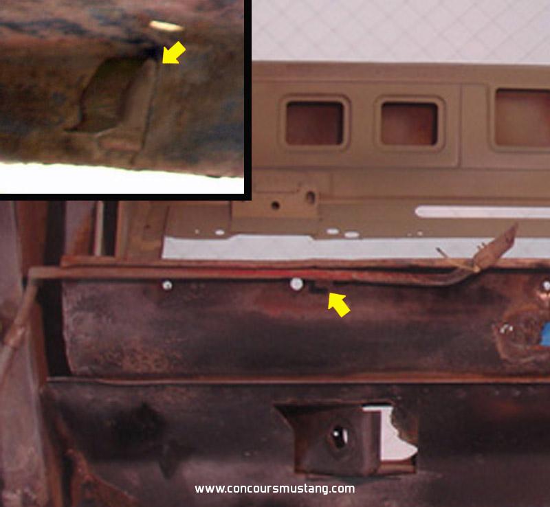
Was looking fro a picture of a fuel line retainer for another thread so while looking I collected pictures of the other retainers as well as the routing so figured I would post so that members would have access to the information. Routing should be the same for the other two plants. Hardware such as retaining bolts/screws and hose clamps will differ
Hope this helps others
The front sections (from inner fender hole to the hose behind the drivers side torque box) were different depending on if the car was a 6 cylinder or a V8
6 cylinder cars - notice the unused hole that the V8's use has a simple rubber plug like used on all the other unused holes in the inner fender panels
FL1-
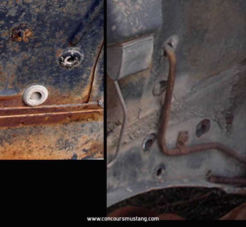
V8 cylinder cars - notice the unused hole that the 6 cylinders use has a simple rubber plug like used on all the other unused holes in the inner fender panels
FL2-
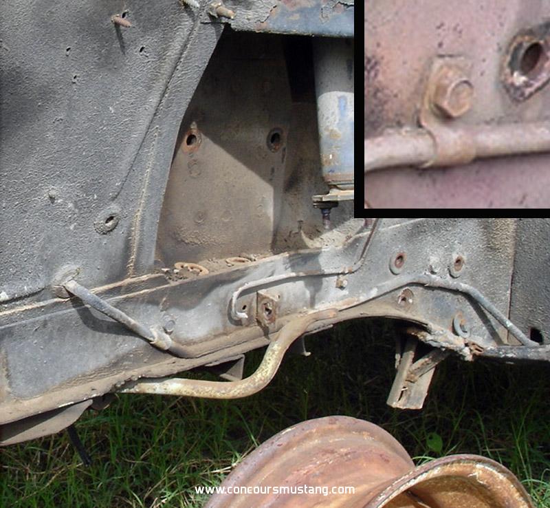
The rest was shared with all engine sizes and with staggered and non staggered rear shock equipped Mustangs and Shelby's
Entering the drivers side torque box
FL3-
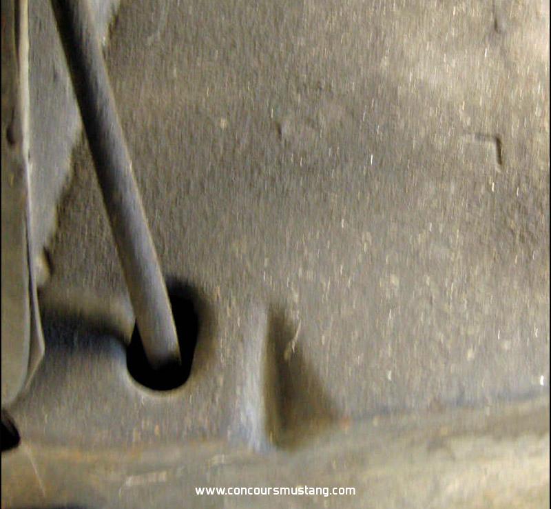
Exiting the torque box
FL4-
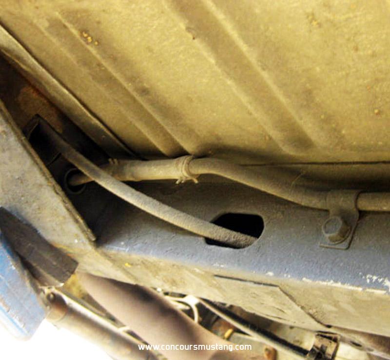
Down and along the drivers side rocker panel. What retainer (clip and attaching hardware) differs depending on body style.
FL5-
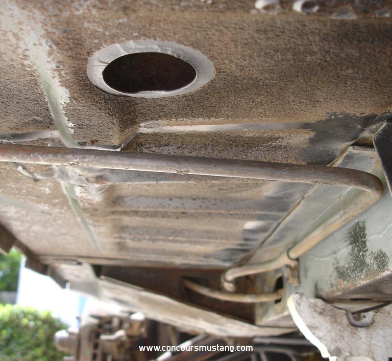
FL6- Coupe and fastback/sportroof
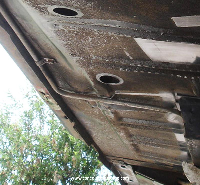
FL7- Convertible
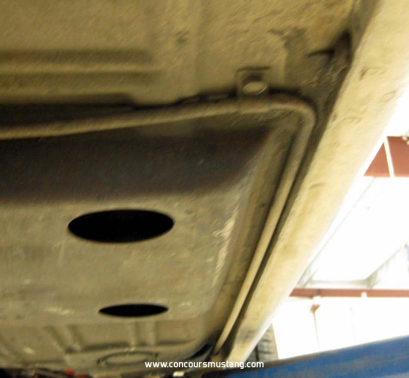
To the rocker panel just outward from the rear spring torque box
FL8-
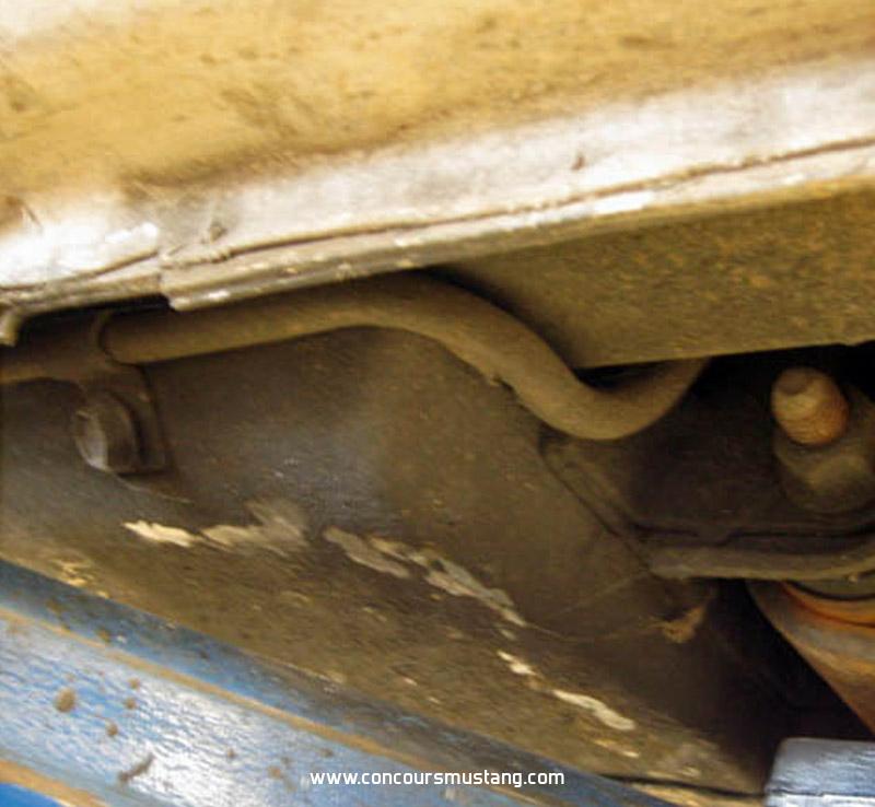
Up and over the rearend, following the curve of the frame rail and floor
FL9-
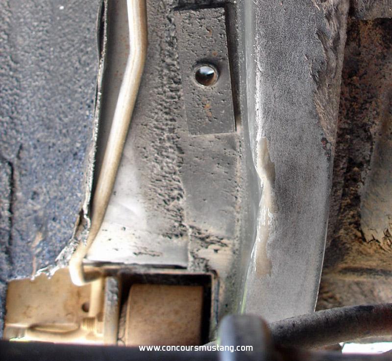
Where it bends and turns inward towards the gas tank sending unit
FL10-
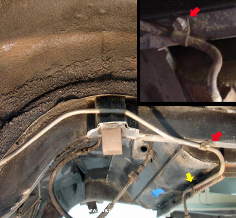
Odd sheet metal retainer is the last one before the line connects (with a rubber fuel line) to the sending unit
FL11-
